Sample Navigation Lessons
The Conventional Airspeed Indicator
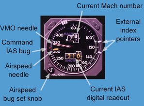
| General This type of instrument is that found in non-EFIS aircraft, and in EFIS aircraft as a standby airspeed indicator in case of EFIS failure. We will discuss the various readouts and relevance of needles, pointers, etc. Firstly it is important that you understand that the airspeed readings are Indicated Airspeed (IAS), not True Airspeed (TAS). Some more modern aircraft have any instrument and position errors automatically calibrated out (removed) by the Central Air Data Computer, and thus readings taken from this gauge would then be Calibrated Airspeed (CAS), or as it is sometimes called Rectified Airspeed (RAS).
VMO needle This is sometimes referred to as the "Barbers Pole," as it is usually painted with red and white stripes. Red means danger, and flying in excess of this speed is extremely unwise, even in smooth air. VMO by definition is the maximum operating speed expressed as an IAS. This needle could just as easily be called a VMO/MMO needle, as it will indicate the IAS which would produce an exceedance of the maximum operating Mach number (MMO) when above VMO/MMO "Changeover Level". If VMO for this particular aircraft type was say 340 KIAS, and MMO was say Mach 0.85, then the needle would stay at glued to 340 KIAS during the climb up to VMO/MMO Changeover Level (FL280 with this combination), then would fall thereafter as the needle now represents MMO. Remember that climbing at a fixed Mach number produces decreasing IAS values as altitude is gained. (Refer to some of the previous training editorials on airspeed/Mach number relationships). If VMO or MMO is exceeded an aural warning will sound in the cockpit, the volume of which is enough to wake the dead. The only way you can silence the warning is to slow the aircraft down to below the VMO/MMO limit speed. Command Airspeed Bug This is the speed you command the aircraft to fly at. The autothrottle will work in association to produce this speed for you (assuming you engage the autothrottle that is). The bug value can be set using the Command Airspeed Bug Set Knob. On some aircraft such as the B767/A320 the value is set in the Airspeed Window on the Autopilot/Flight Director Mode Control Panel, sometimes referred to as the "Glareshield Panel", rather than being set using a gauge mounted knob.
Airspeed needle Obviously, if you are not to exceed VMO or MMO you had better keep the airspeed needle at a value less the that pointed at by the VMO/MMO needle. Current Airspeed Digital readout This simply display’s the value that the IAS needle is currently pointing at. It is easier to read and interpret quickly than is the needle itself. In this case the IAS needle must be pointing at 310 kt. In older aircraft such as the B727 (non-EFIS), the digital readout was basically a rotating drum with numbers painted on it. Later aircraft used Liquid Crystal Digital displays such as that found on your common pocket calculator. Current Mach number Digital readout Identical to the Airspeed digital readout, only showing the aircraft’s current Mach number. If you are climbing at a fixed IAS, the Mach number value will be increasing as altitude is gained. External index pointers These are set using your finger. They are used as a quick reference to display the calculated values of such things as V1, Vr, V2, and approach speed Vref. Setting these help you quickly reference the position of the airspeed needle to such datum values, making scanning much quicker and more accurate. |
The Conventional
Radio Magnetic Indicator
(RMI)
| General:
This instrument is found in most airliner cockpits, and quite a few turbine powered light aircraft such as the Beechcraft King Air, Cessna Conquest etc. It is basically a combination of the fixed card ADF, and the Direction Indicator (DI), and it affords a better presentation of your bearing to, or from the ground beacon. It can be tuned to either a VOR, or an NDB ground beacon and usually two needles (called 1 & 2). Either needle can be set to VOR or NDB. Orientation: The needle heads point TO the ground station, the tail representing the bearing of the aircraft FROM the station. In the diagram, needle 1 (the yellow one) is tuned to a VOR station, and the bearing TO the station is 015 magnetic. The aircraft’s bearing FROM the station (called a radial) is 195 magnetic. To fly TO the VOR, the pilot would hold a heading of 015 magnetic in nil wind conditions. Needle 2 is tuned to an NDB. The track TO the NDB is 345 magnetic. When talking of the aircraft bearing from an NDB we use the term “bearing FROM” the station. The aircraft’s bearing from the NDB is 165 magnetic. The compass card is automatically and continuously aligned with magnetic north at the aircraft location by means of a detector in the wing or tail, called a “flux valve” (also referred to as a “flux gate”). This saves you as pilot of the need to regularly check that the is aligned with the magnetic compass, something you would normally do every 15 minutes in an aircraft not fitted with a flux valve. Flux valves will be the subject of another training editorial in the near future. Refer to the diagram for display information.
Item a: In this case 53.3 nm. Item b: Item c: Item d: Item e: Item f: Item g: Item h: Item i: Item j: Points to note: 1. The RMI does NOT need a TO/FROM flag as does the VOR and HSI, as there is no 180 degree ambiguity. The aircraft is always on the tail of the needles. Bearing TO the station is that indicated by the head of the needles. 2. Modern airliners usually have an HSI and an RMI display for each of the two pilots. To ensure that one RMI and one HSI are available in the cockpit following failure of one of the two flux valves, they are cross wired such that the Captains HSI is wired to the left flux valve, as is the First Officers RMI. The Captains RMI is wired to the right flux valve, as is the First Officers HSI. Should say the left flux valve fail, the Captain would lose heading information to his HSI, and the First Officer would lose his RMI. This type of wiring method is used to achieve redundancy, and is called “Bootstrapping”. |
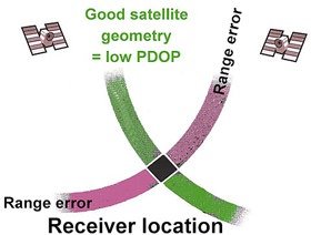
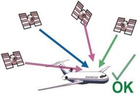
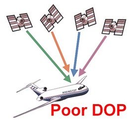
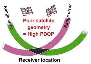
GPS Position Dilution of Precision
|
For more information please email Rob Avery
Home
| ATPL
Courses | Pilot Training Books (All
licence levels) |
Training editorials
Latest Product Releases | Aircraft quiz
page | Internet ATPL Courses
FAQ | Training Specials | Conversion
to Australian ATPL